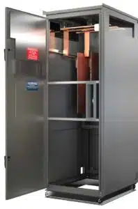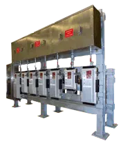
What are Medium-Voltage Load Interrupter Switches?
Medium-Voltage Load Interrupter Switches are installed so that you can safely offer a primary disconnect for a Medium-Voltage electrical systems. These switches are suitable for circumstances where there is no requirement of a circuit breaker. Load Interrupter Switches tend to be a more cost effective solution to Medium-Voltage Drawout Breaker Style Metal Clad Switchgear. These Medium-Voltage switches come in fused or non-fused and are typically used for the primary side protection of a Medium voltage transformer.
Why do we need Medium-Voltage Load Interrupter Switches?
Medium-Voltage Load Interrupter Switches are used to safely disconnect power from down stream equipment, while also adding a layer of protection to the equipment it is hooked up to.
In electrical systems, a interrupter device is used to stop a steady flow of current and with Medium-Voltage Load Interrupter Switches, it is quite similar. The current flow is disrupted by opening the switch. This is done mechanically by switching a handle opening the blades of the switch or the switch may have a motor operator to remotely open the switch, typically with push buttons a good distance away from the switch. Opening the blades of the switch disconnects the power by separating the switches internal contacts. The switch is then locked-out in the Open position using a lock-out-tag-out procedure. A lock-out-tag-out procedure ensures no one accidentally turns the switch on, or closes the switch, while personnel are working on down stream equipment.
Advantages of Medium-Voltage Load Interrupter Switches
Medium-Voltage Load Interrupter Switches have a lot of advantages, and before you install one, it is important to know how it can benefit you in the long run. Here is a list of advantages of Medium-Voltage Load Interrupter Switches:
- Capacity to support applications that allowed fused protection instead of vacuum breaker protection
- Fused & Non-Fused Applications
- Main-Tie-Main Applications
- Can be custom designed to fit in an area where there is limited space
- Custom indoor & outdoor enclosures, including stainless steel
- Ability to work with current limiting fused protection ranging from 0.6kV – 38kV
- Work in both vertical positions as well as horizontal positions
- Economical solution for medium voltage transformer protection
- Utility metering with a main switch
- Smart Grid Ready
- Voltage class ranging from 2400V to 38kV
- Custom no load break switches up to 5000A, continuous load interrupting ratings of 600A & 1200A
- The main buss has a 600-ampere rating, but there is also a 3000-ampere buss
- Fuses using current-limiting or fuses made of boric acid
- Manual or remote motor-operated applications
- Duplex load break switch configurations for alternative feed selection
Can a Medium-Voltage Load Interrupter Switches interrupt a fault current?
As load interrupter switches are neither designed nor tested for interrupting fault currents on electrical systems, they should not be used to interrupt fault currents, phase, or ground. Doing so in your factory or workplace can become hazardous in the long run.
An earthing switch is very important in this case as it will help ground the excessive charge in a power line after it has been detached from the source. After the circuit has been broken or opened by the circuit breaker and isolator, a residual charge is always present in the circuit. The charge is normally discharged using an earthing switch. It is completely safe and helps in the disposal of excess current.
If you are using Medium-Voltage Load Interrupter Switches, it is probably the safest option to choose because they are all fault protected and reliable. All the switches come with a metal enclosed assembly which consists of multiple switches ranging from 5kV to 38kV. These switches are generally used all across, which include commercial spaces, mining, utility, industrial, data center, and health care sectors.
If you are setting up a new industrial facility or substation, then having Medium-Voltage Load Interrupter Switches is quite important. We at Spike Electric will help you with all your needs. We will help you to secure your facility and prevent any hazardous accidents in the future. We provide a complete electrical solution for industrial and commercial areas making us a trusted medium voltage switch manufacturer.
Written by: Cole Attaway
Cole Attaway is the founder and CEO of Spike Electric Controls. Spike's mission is to improve the accessibility and delivery of industrial electrical gear for clients nationwide. Spike solutions result in reduced unplanned downtime, less overtime, and greater operational efficiencies.


