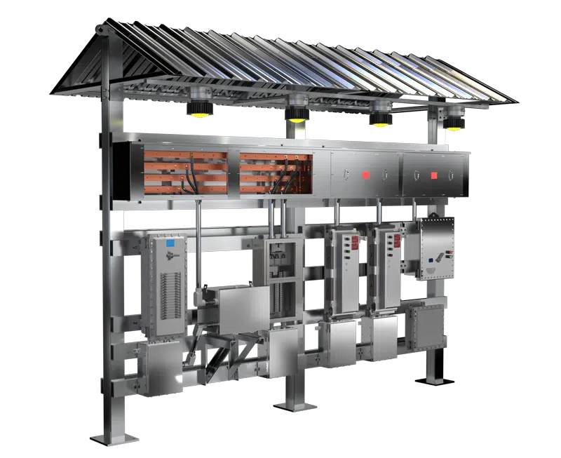
Ensuring that hazardous location (HazLoc) switchracks meet stringent IEEE and UL compliance standards requires thorough validation processes during installation, commissioning, and ongoing maintenance. Proper validation safeguards not only personnel and facilities but also enhances long-term operational reliability. Drawing from IEEE guidelines and practical industry experience, particularly from companies like Spike Electric Controls, this blog outlines a comprehensive real-world checklist engineers and technicians should follow for HazLoc switchrack validation.
Pre-Installation Checklist
Validation begins with the proper handling and preparation before installation. Key items include:
- Shipping Inspection: Upon arrival, verify equipment against the original purchase order and shipping documentation.
- Physical Inspection: Confirm no physical damage occurred during shipping. Inspect bus ducts, structural members, enclosures, and components for dents, scratches, and deformities.
- Documentation Verification: Ensure all equipment arrives with complete documentation, including equipment manuals, one-line diagrams, and factory acceptance test (FAT) results.
Structural Integrity and Mechanical Checks
Proper structural integrity is fundamental for switchrack safety. Verify:
- Weld Integrity: Inspect all structural welds visually and through non-destructive testing (NDT) methods if specified.
- Structural Alignment: Confirm structural components such as beams and supports are square, level, and correctly aligned.
- Bolt Tightness: Ensure all structural bolts are correctly torqued according to the manufacturer’s specifications.
Electrical Component and Wiring Validation
The integrity of electrical components directly impacts operational safety. Essential checks include:
- Bus Bar Inspection: Visually inspect bus bars for proper insulation, plating (tin or silver), and correct spacing.
- Circuit Breaker Ratings: Confirm breaker ratings and trip settings match the project specifications and the coordination study.
- Wire and Cable Integrity: Check cables for insulation damage, correct type (XHHW, rated for 90°C), proper sizing, and correct termination torque.
- Conduit Installation: Inspect all conduits for correct installation, appropriate sealing methods, and alignment with NEC standards.
Grounding System Verification
Grounding systems must meet IEEE and NEC guidelines:
- Ground Continuity Tests: Perform continuity tests to ensure grounding paths are intact and effective.
- Ground Resistance Measurement: Measure and document grounding system resistance, ensuring compliance with design specifications.
Equipment-Specific Checks
Each type of equipment mounted on the switchrack requires targeted validation:
- Motor Starters: Confirm starters are correctly sized and rated, verify overload relay settings, and conduct functional testing of start/stop and emergency stop controls.
- Lighting Panels and Transformers: Inspect for proper wiring, grounding, and verify correct load distribution and protective device ratings.
- Protective Devices: Validate proper device settings based on coordination studies. Conduct functional testing for breakers and protective relays.
Explosion-Proof Enclosures and Components
In hazardous locations, explosion-proof integrity is non-negotiable:
- Seal Integrity: Ensure all conduit seals are correctly poured and cured according to manufacturer guidelines and NEC standards.
- Explosion-Proof Ratings: Verify enclosures and associated control devices (handles, pilot lights) are from the same manufacturer, correctly rated, and compliant with UL or NRTL certifications.
- Machined Surface Integrity: Inspect enclosure machined surfaces carefully to ensure no damage or contamination could compromise explosion-proof integrity.
Commissioning and Functional Testing
Before energizing the equipment, comprehensive functional tests must be completed:
- Insulation Resistance Testing: Conduct insulation resistance (megger) tests on all cables, bus ducts, and equipment connections.
- Torque Verification: Recheck and verify torque values of all electrical connections.
- Functional Operation Tests: Run complete functional tests for circuit breakers, motor controls, lighting systems, and interlocks.
- Arc Flash Assessment: Ensure all equipment is labeled appropriately with arc-flash hazard boundaries and necessary personal protective equipment (PPE) requirements.
Post-Installation and Maintenance Checks
Routine inspections are vital for long-term operational reliability:
- Periodic Thermal Imaging: Conduct regular infrared inspections to detect hot spots indicative of loose connections or failing components.
- Routine Corrosion Inspection: Regularly inspect structural and electrical components for signs of corrosion, especially in harsh environments.
- Seals and Gaskets Checks: Periodically inspect explosion-proof seals and enclosure gaskets for integrity and signs of deterioration.
- Component Replacement Logs: Maintain accurate records of any replaced components, noting replacement dates and ensuring adherence to original specifications.
Safety and Compliance Audits
Regular safety and compliance audits help maintain ongoing validation:
- Compliance Documentation: Ensure all documentation and equipment certifications remain updated and readily accessible for audits.
- Safety Training Records: Maintain and regularly update safety training logs for all personnel involved in switchrack operations and maintenance.
Seals, Gaskets, and Proper Closure of NEMA 7 Enclosures
- Regularly inspect explosion-proof seals and enclosure gaskets at least annually or after major maintenance events, complementing visual inspections with tactile checks to ensure gasket elasticity and effective sealing. Additionally, for NEMA 7 bolted enclosures, ensure proper closure following manufacturer guidelines, specifically verifying that enclosure covers are evenly secured and bolts are tightened according to specified torque requirements. Reference Eaton’s instruction sheet for precise torque settings and procedures to maintain the integrity of explosion-proof ratings and ensure continued compliance and safet
Continuous Improvement Practices
Validation is a dynamic process that benefits from continuous improvement:
- Feedback Loops: Establish regular feedback channels between operational teams, maintenance personnel, and equipment manufacturers for continuous improvement.
- Periodic Review Meetings: Regularly scheduled meetings to review inspection outcomes, safety incidents, and compliance status help maintain high safety standards.
Conclusion: Ensuring Long-Term Reliability and Safety
A meticulous validation checklist, grounded in IEEE guidelines and practical field experience, ensures that HazLoc switchrack installations remain safe, compliant, and reliable over their operational lifecycle. Organizations adopting these validation practices not only safeguard their personnel and assets but also significantly enhance overall operational effectiveness and financial sustainability. Through ongoing attention to detail, adherence to proven standards, and continuous improvement, facilities can confidently manage their hazardous location electrical infrastructure, ensuring maximum safety, compliance, and long-term reliability.


