
PowerConnect™ Busway & Bus Systems
A modular U.S.-market platform for moving high current from source equipment to distributed loads with a compact footprint, flexible routing, and coordinated tap-off protection.
Spike is developing feeder, plug-in, and vertical riser busway for 60 Hz power systems through 600 V, supported by breaker, fusible, non-fusible, cable-tap, and metered plug units. Final ratings and certification marks will be published after completion of the NRTL qualification program.
Feeder • Plug-In • Riser | Copper & Aluminum Options | Breaker • Fused • Non-Fused | U.S. Qualification Program
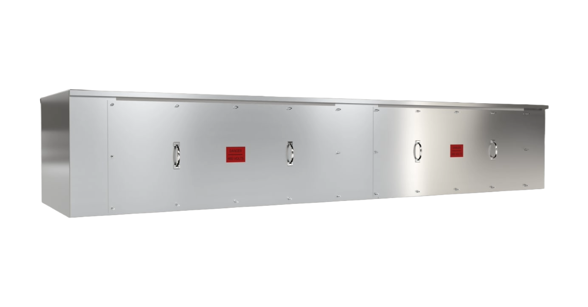
Power Connect Bussed Gutter

LV & MV Cable / Generator Tap Boxes
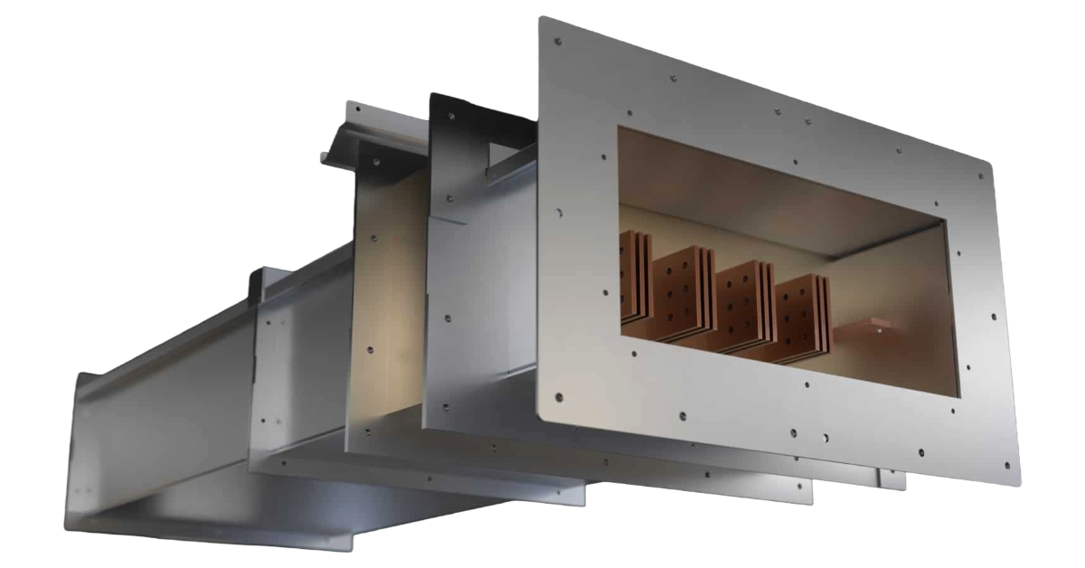
Segregated & Non-Segregated Bus Duct
One platform, built around the way U.S. projects are designed.
Organize the page by application and customer need—not by the supplier’s internal series names. Every card below should lead to a focused subpage as the product line is qualified.
Feeder Busway
High-capacity source-to-load distribution between transformers, switchgear, switchboards, motor control centers, and major equipment.
Plug-In Busway
Distributed power with standardized outlets for adding or relocating approved tap-off units without reworking the full feeder route.
Vertical Riser Busway
Space-efficient multi-floor distribution with engineered supports, expansion provisions, floor penetrations, and plug orientation.
Bus Plugs & Tap-Off Units
Breaker, fusible, non-fusible, unfused cable-tap, metered, and communicating units engineered as part of the same controlled system.
Fittings & Accessories
Elbows, offsets, tees, reducers, expansion sections, end feeds, flanged ends, hangers, floor supports, and transition sections.
Metal-Enclosed Bus
Custom nonsegregated, segregated, isolated-phase, and cable-bus solutions for utility, generation, and heavy industrial applications.
A cleaner path from source equipment to distributed loads.
Busway provides a factory-engineered alternative to large cable-and-conduit runs where installation speed, compact routing, controlled joints, and future expansion matter.
Less field-intensive routing
Factory-built sections, fittings, and joints can reduce large conduit runs, pulling, and repeated field terminations.
More adaptable distribution
Approved plug units can support planned load additions and relocations at defined outlets.
Compact use of electrical space
Useful in crowded electrical rooms, risers, manufacturing areas, and overhead pathways.
Integrated system performance
Busway, fittings, joints, plugs, and protective devices are selected and evaluated as a complete system.
Better expansion planning
Documented layouts, outlet locations, and field-measurement procedures support additions and future phases.
Bus plugs engineered for the complete system.
Do not describe the product as “breaker agnostic.” Publish only the exact breaker, switch, fuse, lug, and accessory combinations included in Spike’s compatibility matrix and NRTL investigation.
Circuit-Breaker Plugs
Planned range through 1000 A. Approved breaker families, AIC by voltage, trips, and accessories must be published by exact configuration.
Fusible Switch Plugs
Class J and R launch configurations, with Class L high-current options where the complete assembly is qualified.
Non-Fusible Disconnects
Load-break isolation with documented upstream overcurrent-protection requirements and approved device combinations.
Cable Tap Boxes
Unfused connection and transition units with listed lugs, barriers, conductor ranges, torque data, and wire-bending space.
Metered & Communicating
Branch monitoring, alarms, and communications for industrial, commercial, and critical-power applications.
Start with your one-line and building layout
Our team can help you choose the right configuration for your facility or project.
Designed around common North American power systems.
The values below are recommended launch targets. The public website must replace “planned” with final tested ratings only after the NRTL report and controlled product matrix are complete.
600 V — maximum system-voltage class planned
60 Hz — North American power-frequency design basis
225–5000 A — recommended launch current range
Cu / Al — copper and aluminum conductor options
Build the U.S. product story around visible, verifiable safety features.
These claims belong on the live website only after the final design and test program confirm them across the approved plug-unit family.
Ground-first / break-last engagement
The grounding connection is established before phase conductors and remains connected until after phase separation.
Mechanical polarization
Prevents an incompatible voltage, phase arrangement, or plug orientation from being installed.
ON-position interlock
Prevents insertion or removal while the protective or disconnecting device is in the ON position.
Shuttered or barriered outlets
Limits access to energized bus at unused outlets and during the approved installation sequence.
Positive mechanical retention
Resists vibration, short-circuit forces, and accidental release in horizontal and vertical applications.
Clear operating status
ON, OFF, and TRIPPED condition is visible from the normal operating position.
Flexible power distribution for demanding facilities.
Use distinct original renderings for each market. Keep the product geometry consistent across all scenes so the page feels like one engineered platform—not stock photography.
Manufacturing & Process Facilities
High-current distribution for process lines, machine centers, and plant expansions.
Data Centers & Critical Power
Scalable busway paths for white space, UPS, and critical distribution.
Commercial & High-Rise Buildings
Riser and horizontal distribution for multi-tenant and high-rise floors.
Hospitals & Institutional Facilities
Reliable distribution for hospitals, labs, and institutional campuses.
EV Charging & Fleet Infrastructure
Feeder and branch paths for EV charging and fleet depots.
Utility, Energy & Packaged Systems
Packaged and utility-scale distribution for energy and generation sites.
From one-line and layout through installation support.
Position Spike as the accountable U.S. engineering and project interface—not simply a reseller of imported busway sections.
01 · Application and one-line review
Confirm system voltage, ampacity, available fault current, source equipment, loads, routing, and environmental conditions.
02 · Layout, routing, and BIM/CAD coordination
Develop the run, fittings, supports, clearances, penetrations, and interfaces with transformers, switchgear, and loads.
03 · Protection and plug-unit selection
Coordinate approved breakers, fuses, disconnects, metering, communications, lugs, and branch-circuit requirements.
04 · Submittals and field verification
Provide approval drawings, schedules, installation information, and field measurement for final or missing-link sections.
05 · Commissioning and future expansion
Support installation, torque verification, baseline inspection, spare plugs, additions, and documented changes.
Publish one simple ratings table.
Customers should not have to search several catalogs to understand the platform. After qualification, replace every “planned” or “under evaluation” entry with the exact tested configuration and link to the full technical guide.
Publication gate: Never display a UL, CSA, ETL, NEMA enclosure, short-circuit, breaker-compatibility, or arc-resistant claim until the exact product configuration and claim are documented by Spike engineering and the appropriate certification/test record.
| System voltage | Through 600 V planned; 208Y/120 V, 240 V, 480Y/277 V, 480 V, and selected 600 V applications. |
| Frequency | 60 Hz. |
| Configurations | Feeder, plug-in, vertical riser, and project-specific transition sections. |
| Continuous current | 225–5000 A recommended launch range, subject to final certification. |
| Conductors | Copper and aluminum options. |
| Electrical system | Three-phase, three-wire and three-phase, four-wire. |
| Neutral options | 100% neutral; 200% neutral option under evaluation. |
| Grounding | Housing ground; integral equipment grounding conductor; isolated-ground option under evaluation. |
| Environmental | Indoor, sprinkler-resistant, and NEMA 3R outdoor configurations only where tested and listed. |
| Tap-off units | Circuit breaker, fusible switch, non-fusible disconnect, cable tap, metered, and communicating options. |
| Short-circuit performance | Publish by voltage, ampacity, conductor, and protective-device configuration after testing. |
| Standards path | ANSI/UL 857; CSA C22.2 No. 27; applicable NEC/NFPA 70 busway requirements. |
Build the technical support package with the product.
Do not launch empty download buttons. Publish each resource only when the corresponding controlled document is complete.
Product Overview
Portfolio, applications, ratings, and selection guidance. (Coming soon)
Guide Specification
Editable U.S. project specification. (Coming soon)
CAD & BIM Library
Straights, fittings, supports, plugs, and connections. (Coming soon)
Bus Plug Compatibility Matrix
Exact approved breakers, switches, fuses, ratings, and accessories. (Required)
Installation & Maintenance Manual
Receiving, storage, installation, torque, inspection, and service. (Required)
Quote & Layout Checklist
One-line, fault current, routing, environment, and load schedule inputs. (Launch first)
Answer the questions engineers ask before they request a quote.
What is the difference between feeder and plug-in busway?
Feeder busway carries power between major source and load equipment without distributed outlets. Plug-in busway includes approved outlet locations that accept compatible tap-off units for branch loads.
Can the system use breaker, fused, and non-fused plug units?
The planned U.S. platform includes circuit-breaker, fusible-switch, non-fusible-disconnect, and unfused cable-tap configurations. Availability will depend on the final approved ampere range and certification matrix.
Which breaker brands can be installed?
Only the manufacturers, breaker families, frames, trip units, interrupting ratings, lugs, and accessories identified in Spike’s published compatibility matrix may be used. Physical fit alone does not establish approval.
Can Spike support existing-building measurements and field changes?
Yes. The planned project workflow includes layout review, field verification, missing-link sections, approval drawings, installation support, and controlled future additions.
Is the product UL listed?
Pre-launch answer: “The U.S. product is in engineering and NRTL qualification. Spike will publish the exact listing mark, file number, ratings, and approved configurations after completion.”